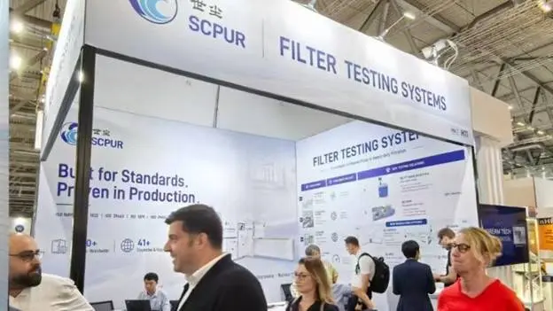


Testing an engine air cleaner involves more than supplying dust and measuring pressure drop. A compliant test system must accurately control airflow and dust concentration, collect the dust that penetrates the test air cleaner, record weighing data and calculate performance at the required test stages.
ISO 5011:2025 establishes uniform laboratory procedures for comparing inlet air cleaning equipment used with internal combustion engines and compressors. Its principal performance characteristics include:
- Airflow restriction or differential pressure
- Initial dust collection efficiency
- Full-life dust collection efficiency
- Incremental dust collection efficiency
- Dust capacity
- Oil carry-over for oil-bath air cleaners
This guide focuses mainly on equipment for testing dry-type air cleaners. Oil-bath air cleaners require additional equipment and a separate oil carry-over test configuration.
What Does an ISO 5011 Test System Measure?
An engine air cleaner test system should support several distinct measurements. These tests serve different purposes and should not be treated as one continuous test sequence in every case.
1. Airflow Restriction
The restriction test measures the resistance of the air cleaner at a series of specified airflow rates.
The result is normally presented as an airflow–restriction curve. This curve shows how the air cleaner affects the air supply to the engine or compressor across its intended operating range.
Accurate restriction testing depends on:
- Stable airflow control
- Calibrated airflow measurement
- Correct pressure measurement locations
- Suitable differential pressure ranges
- Proper installation and sealing of the test air cleaner
- Recording of temperature, pressure and other required air conditions
A test system must provide sufficient airflow and pressure capability for both a clean filter and a filter approaching its specified final restriction.
2. Initial Dust Efficiency
Initial dust efficiency evaluates the gravimetric dust collection performance of a clean air cleaner during the initial test period.
This is not a particle-counting efficiency test. The result is based on the mass of standardized test dust supplied to the air cleaner and the mass of dust that passes through it.
An absolute filter installed downstream collects the penetrating dust. The absolute filter is weighed before and after the applicable test period, allowing the downstream dust mass to be determined.
The result indicates how effectively the new air cleaner captures the specified test dust under controlled laboratory conditions.
3. Full-Life Dust Efficiency
The full-life test evaluates the overall gravimetric efficiency of the air cleaner as dust loading continues to the specified endpoint.
During the test:
- Airflow is maintained at the required test condition.
- Standardized test dust is supplied at a controlled concentration.
- Air cleaner restriction is monitored.
- Downstream dust is collected by the absolute filter.
- Weighing data are recorded at the required stages.
- Testing continues until the specified termination condition is reached.
The endpoint is generally related to a specified final restriction or another condition defined by the applicable test programme. It should not simply be described as filter “failure.”
Full-life efficiency provides a standardized basis for comparing products, but it does not directly predict filtration efficiency over every real operating cycle.
4. Incremental Dust Efficiency
Incremental efficiency shows how gravimetric efficiency changes during different stages of dust loading.
Instead of reporting only one result for the complete test, the dust-loading process is divided into specified intervals. At each interval, the mass of dust supplied and the mass collected downstream are used to determine the corresponding incremental efficiency.
This helps engineers evaluate whether efficiency:
- Remains stable during loading
- Increases as a dust cake develops
- Changes unexpectedly at a particular loading stage
- Is affected by sealing or structural problems
The efficiency is calculated at the specified intervals; it is not measured continuously in real time.
5. Dust Capacity
Dust capacity is the quantity of test dust retained by the air cleaner up to the specified test endpoint.
It is an important comparative performance characteristic, but it should not be described as the quantity of dust held “before failure.” Reaching the final test restriction does not necessarily mean that the air cleaner has structurally failed.
Laboratory dust capacity also does not directly equal field service life. Actual replacement intervals can be influenced by:
- Atmospheric dust concentration
- Particle size and composition
- Humidity and water exposure
- Vehicle or machine operating conditions
- Vibration and installation quality
- Maintenance practices
- Changes in airflow demand
ISO 5011 testing provides repeatable laboratory comparison data rather than a complete simulation of every service environment.
How Is Gravimetric Efficiency Measured?
Understanding the weighing principle is essential when selecting ISO 5011 test equipment.
A typical dry-type test arrangement includes:
- A controlled airflow source
- A standardized dust feeder
- The test air cleaner
- A downstream absolute filter
- Restriction and airflow measurement
- Precision weighing equipment
- Data acquisition and calculation software
A known quantity of test dust is supplied upstream of the air cleaner. Most of the dust is retained by the test air cleaner, while the penetrating portion is collected by the downstream absolute filter.
The absolute filter is weighed under controlled conditions before and after the relevant test stage. These mass measurements are used with the supplied dust data to calculate gravimetric efficiency.
Because the downstream dust mass may be very small, the following factors are particularly important:
- Balance capacity and resolution
- Stable weighing conditions
- Consistent absolute-filter handling
- Prevention of dust loss during removal and transport
- Correct recording of initial and final mass
- Control of moisture-related mass changes
- Traceable association between each weighing result and test stage
Automated entry of balance readings can reduce transcription errors, but proper handling and weighing procedures remain necessary.
Main Components of Engine Air Filter Testing Equipment
Airflow Generation and Control
The airflow system must cover the rated flow range of the intended air cleaners while overcoming the resistance of the test duct, test air cleaner, absolute filter and other system components.
The fan and control system should provide:
- Stable airflow at each test point
- Sufficient pressure capability at the final test restriction
- Smooth adjustment over the required range
- Repeatable control during long dust-loading tests
- Safe response to excessive restriction or abnormal conditions
Calibrated Airflow Measurement
Airflow measurement is one of the fundamental measurements in the system.
A suitable system may use calibrated nozzles or another recognized flow-measurement method. Where several nozzles are provided, the appropriate measurement range should be selected according to the test airflow.
The airflow measurement system should be evaluated for:
- Measurement range
- Accuracy
- Calibration traceability
- Pressure and temperature compensation
- Automatic or manual range selection
- Stability throughout dust loading
Test Dust Feeding System
The dust feeder must deliver the selected test dust at a controlled and repeatable rate.
Depending on the agreed test method, dust such as ISO 12103-1 A2 Fine or A4 Coarse may be used. The applicable dust type, concentration and feeding rate should be defined before the test.
Important feeder characteristics include:
- Stable feeding rate
- Suitable range for different airflow conditions
- Uniform dust dispersion
- Minimal dust accumulation in the feed path
- Easy cleaning between tests
- Verification of the actual dust quantity supplied
An average feeding rate alone is not sufficient if the dust delivery fluctuates significantly during the test.
Test Air Cleaner Mounting Section
The mounting arrangement must accommodate the air cleaner without allowing bypass leakage.
Different products may require:
- Round filter adapters
- Rectangular mounting frames
- Complete air-cleaner housing connections
- Custom inlet and outlet transitions
- Adjustable supports
- Sealing or clamping fixtures
The adapter should support the product without deforming it and should reproduce the intended airflow direction. Leakage around the adapter can cause an invalid efficiency result.
No test system can support literally unrestricted filter dimensions. Filter size, connection geometry, rated airflow and available installation space should always be reviewed before the system configuration is confirmed.
Absolute Filter Assembly
The downstream absolute filter collects the dust penetrating the test air cleaner.
Its design should allow:
- Sufficient collection efficiency
- Secure sealing
- Convenient installation and removal
- Minimal dust loss during handling
- Adequate capacity for the planned test
- Repeatable positioning
- Safe isolation when the filter is weighed or replaced
The absolute filter is a measurement component, not merely an exhaust filter. Its installation and weighing procedure directly influence the calculated efficiency.
Weighing System
Depending on the test procedure and filter configuration, weighing may be required for:
- Test dust supplied
- Absolute filters
- Test air cleaners or filter elements
- Dust recovered from specified components
The weighing equipment should be selected according to the expected mass and required resolution. One balance may not be suitable for both a heavy air cleaner and a lightweight absolute filter.
A practical system may therefore use separate weighing ranges for the test air cleaner and the absolute filter.
Restriction and Environmental Measurement
The system should measure restriction at the required locations and ranges.
Where a wide pressure range is required, using more than one differential pressure range can improve measurement quality at both low and high restriction.
Temperature, atmospheric pressure and humidity should also be recorded when required, because air conditions can affect airflow calculation, dust behaviour and weighing stability.
Control Software and Reporting
Automation can improve repeatability by controlling the test sequence and reducing manual recording. However, automation does not replace calibration or correct test procedures.
Useful software functions include:
- Test profile management
- Automatic Test ID generation
- Airflow setpoint control
- Dust-feeder control
- Restriction monitoring
- Electronic balance data acquisition
- Test-stage identification
- Endpoint detection
- Efficiency and capacity calculation
- Real-time curve display
- Alarm and interlock management
- Raw-data storage
- Report generation
The software should prevent testing from starting when required profile information or test conditions have not been defined.
Typical Dry-Type Air Cleaner Test Process
The exact sequence depends on the selected ISO 5011 test and agreed test plan. A typical full-life efficiency and capacity test may include:
- Record the test air cleaner identification and test conditions.
- Inspect and weigh the required components.
- Install the test air cleaner and verify its sealing.
- Install and record the initial mass of the absolute filter.
- Establish the specified airflow.
- Measure the initial restriction.
- Start controlled dust feeding.
- Monitor airflow, restriction and dust feeding.
- Stop at the specified intervals for the required weighing operations.
- Calculate incremental efficiency where where required.
- Continue loading until the defined endpoint is reached.
- Complete final weighing and calculate full-life efficiency and dust capacity.
- Generate the test report and retain the raw data.
Initial efficiency, restriction and other ISO 5011 tests can require different procedures. Not every test should be represented as the same universal sequence.
Common Sources of Test Error
Unstable Dust Feeding
Variations in the dust feed rate can affect loading behaviour, test duration and the comparability of results.
Air Leakage
Leakage around the test air cleaner, adapter or absolute filter can allow dust to bypass the intended measurement path.
Incorrect Absolute-Filter Handling
Dust loss, contamination or moisture changes during weighing can significantly affect the calculated efficiency.
Inaccurate Airflow Measurement
Incorrect nozzle selection, sensor drift or uncompensated air conditions can change the actual test airflow.
Unsuitable Pressure Range
A pressure sensor selected only for the maximum restriction may provide insufficient resolution at low initial restriction.
Inconsistent Endpoints
Results cannot be compared properly when filters are tested to different final restrictions or termination conditions.
Manual Data Entry
Incorrect association of weights, stages or sample identities can invalidate calculations. Direct acquisition from an electronic balance can reduce this risk.
What to Confirm Before Selecting a Test System
Before specifying engine air filter testing equipment, the laboratory should define:
- Applicable ISO 5011 edition
- Dry-type or oil-bath air cleaner
- Filter element or complete air cleaner assembly
- Minimum, rated and maximum airflow
- Maximum expected restriction
- Filter dimensions and connection geometry
- Required test dust types
- Required dust concentration and feed range
- Initial, full-life and incremental efficiency requirements
- Required absolute-filter configuration
- Weighing ranges and resolution
- Required environmental measurements
- Report format and raw-data requirements
- Calibration and verification requirements
- Space, power and compressed-air conditions
These inputs determine the test duct, fan, flowmeter, dust feeder, weighing system and software configuration.
Manual Operation and Automation
Manual systems can be appropriate for limited test volumes or development work, while automated systems can reduce repetitive operation and improve consistency.
The correct comparison is not simply “manual equals low accuracy” and “automatic equals high accuracy.” Measurement quality depends on:
- System design
- Calibration
- Sensor selection
- Dust-feeding performance
- Leakage control
- Weighing practices
- Software calculations
- Operator training
- Maintenance and verification
Automation is most valuable when it controls repeatable processes while retaining traceable raw data and allowing the operator to verify each critical measurement.
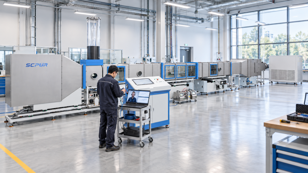
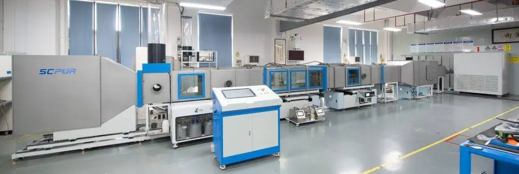
SCPUR SC-5011 Test System
The SCPUR SC-5011 Air Intake Filter Test System is designed for performance testing of dry-type inlet air cleaners used in automotive, heavy-duty and industrial applications.
Depending on the agreed configuration, the system supports:
- Airflow–restriction testing
- Initial gravimetric efficiency
- Full-life gravimetric efficiency
- Incremental efficiency
- Dust capacity
- Controlled test-dust feeding
- Automatic airflow and restriction monitoring
- Electronic weighing data acquisition
- Test-stage calculation
- Curve display and report generation
Adapters and supports can be designed according to the filter dimensions, installation method and rated airflow. The final system configuration should be confirmed against the customer’s products and required test programme.
Conclusion
ISO 5011 testing equipment must do more than generate airflow and feed dust. Reliable results depend on the complete measurement chain—from airflow and dust control to absolute-filter collection, precision weighing, stage calculation and report traceability.
When selecting a system, laboratories should pay particular attention to:
- Test airflow and pressure capability
- Gravimetric efficiency measurement
- Absolute-filter design
- Weighing range and resolution
- Dust-feeding stability
- Adapter sealing
- Endpoint control
- Calibration and data traceability
A correctly configured system provides repeatable laboratory data for comparing air cleaner restriction, dust efficiency and dust capacity. These results support product development and technical evaluation, but they should not be interpreted as a direct prediction of field service life.
Contact SCPUR to discuss your air cleaner dimensions, rated airflow, test dust and required ISO 5011 test functions.
Official Reference
The applicable standard edition and complete test requirements should be confirmed before testing.